Home Next: Feature Detection and Matching
Canny Edge detection is widely used in Image processing, Computer Vision and other image related areas. Here is an implementation of C++ code based on FLTK and .Net2003. Code is available to download here:
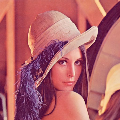
Here I use the formula that is the same as that used in Matlab.
Y = 0.2989 * R + 0.5870 * G + 0.1140 * B
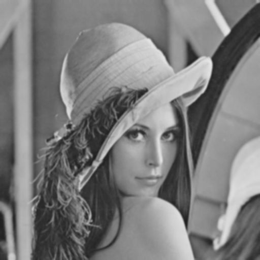
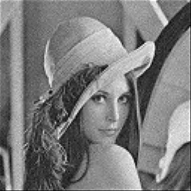
To decrease the influence of noise, I smooth the image using Gaussian Smooth Mask. Here 5*5 mask recommended in Wiki is used.

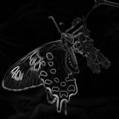
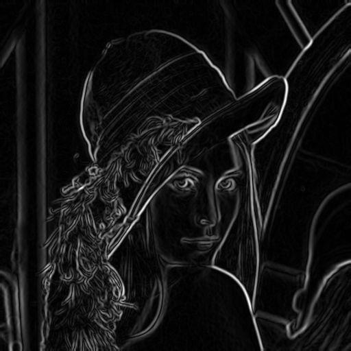
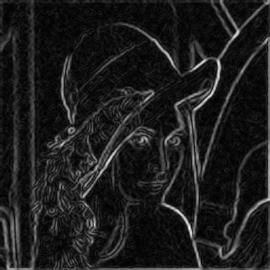
Compute derivatives of the image using vertical and horizaontal Sobel Operator. So we get the derivative along both x and y directions, based on which we can get the final gradient magnitude and the norm direction of the edge. So we get 2 images in this step, one derivative magnitude image and one image recording the gradient directions of correspongding piexels.
|G| = sqrt (G_x^2 + G_y^2)
theta = atan (G_y / G_x)
Note: The boundary of the image should be taken carefully since the sobel operator will be out of the image rang if the center of it is pushed just beyond the boundary pixel. There are many kinds of tricks to overcome it, and here, instead of pad zeros around the image, I copied the magnitude adjancent to the boundary pixel. The other disgusting point is that before doing the division to get theta, we must make sure that G_x is not zero! And when G_x is zero theta should be determined by the mathematic algorithm.
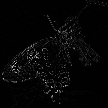
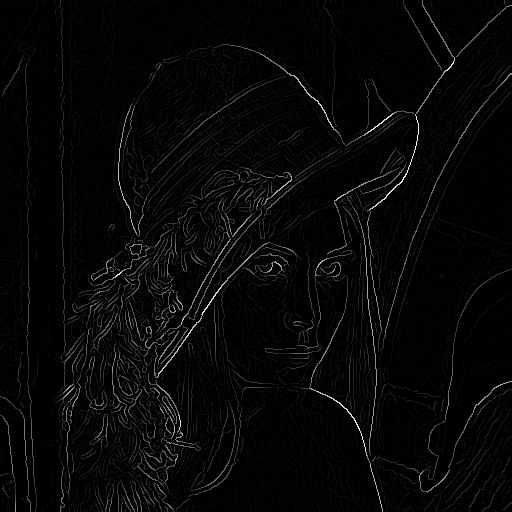
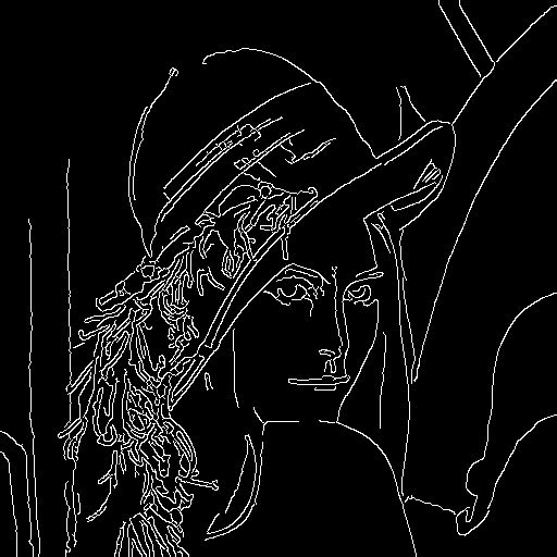
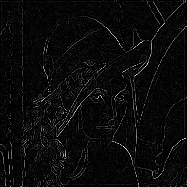
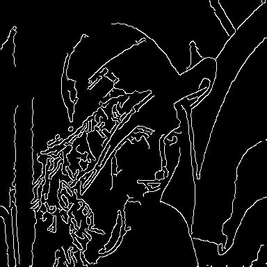
Actually, we have got the coarse edge of the image after the 3rd step, i.e. the magnitude of derivatives accompany with the edge direction information. In this step, firstly the edge direction is grouped into 4 8 directions: [0, 45), [45, 90), [90, 135), [135,180), [180, 225), [225, 270), [270, 315), [315, 360), and then I suppress the non-maximum pixels along the norm of edge using the edge direction information. So the edge will become thiner after non-maximum suppresion as figures below.


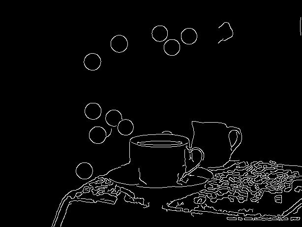
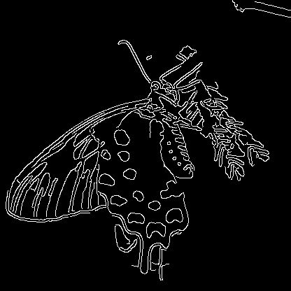
Canny uses hyteresis threshold to fill up the narrow gap along the edge. The output of step 4 is compared to both high threshold T_h and low threshold T_l. Pixels with gray values greater than T_h is set as the initial edge pixels while pixels are set as background if their values are lower than T_l. A following recursive process takes charge of pixels Lying between T_h and T_l. I call them as vibrating pixels. The recurse checks 8-adjancent neighbors of each initial edge pixel to see whether there are vibrating pixels. Vibarating pixels will be added to the initial edge pixel set. This process will go on until all the initial edge pixels have been recursed, and vibrating pixels that have not been visited will be set as background pixel unfortunately.
Note:
1). Though I explained this step in two separate processes, one tranversal of the image is enough while implementing it.
2). It is an interesting problem to determine the two threshhold in this step. Here I take exactly the same method as in Matlab. That is, only a small ratio pixels will become edge pixels at last, so we need consider only a bit larger ratio pixels will be ok. I set this ratio as 90% instead of 70%, which is used in matlab, after some experiments. next, another ratio, 0.2 in my implementation, between the high and low threshold is used to determin the low threshold.
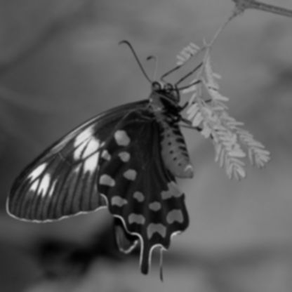
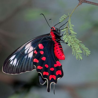
Every row indicates one whole process of an image.
From left to right: Original Image, Presmoothed Image, Gradient Image, Non-maximum Suppressed Image, Final Result.